AN/SPS-3
Description of the radar set, tactical-technical characteristics
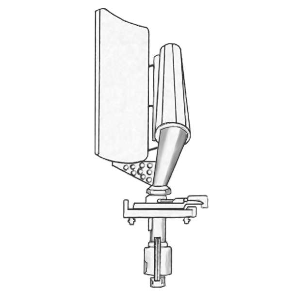
Figure 1: AN/SPS-3, Drawing of the antenna unit
U.S. Naval Research Laboratory
| Specifications | |
|---|---|
| frequency: | 9 003 … 9 168 MHz, and
9 345 … 9 405 MHz ( X-Band) |
| pulse repetition time (PRT): | |
| pulse repetition frequency (PRF): | 3000 or 1500 Hz |
| pulsewidth (τ): | 0.25, 0.33 or 1.33 µs |
| receive time: | |
| dead time: | |
| peak power: | 2×200 kW |
| average power: | |
| instrumented range: | 25 NM (≙ 46 km) |
| range resolution: | |
| accuracy: | |
| beamwidth: | |
| hits per scan: | |
| antenna rotation: | |
| MTBCF: | |
| MTTR: | |
AN/SPS-3
The AN/SPS-3 was an early post-WWII, short range, X-Band naval radar for use on destroyers and larger vessels. It was a hemispherical search radar and utilizes two rapid scanning pencil-type antenna beams, each covering a 40-degree elevation angle sector and full 360-degree azimuth. Slightly different frequencies are used for the two beams (frequency diversity). Each beam had its own transmitter, receiver and waveguide system, but only one antenna system, using a dual Foster Scanner, was required.
The modulator was of the hydrogen thyratron type and was capable of pulsing both magnetrons simultaneously by use of a special dual type pulse transformer. The magnetrons were types 4J50 and 4J78. A so-called synchroscope unit (combined synchronisator and display) containing a 5-inch cathode ray tube and associated circuits was capable of presenting video, trigger, modulator pulse, and STC voltages, as well as functioning as an A-scope with 1/2, 5 and 25 miles sweeps.
It was installed as a pre-production prototype (XN-1) on the USS Northampton CLC-1 in 1954. After this one installation the AN/SPS-3 program was cancelled.
Source: