SRE-M
Description of the radar set, tactical-technical characteristics
| Specifications | |
|---|---|
| frequency: | 1250 … 1350 MHz |
| pulse repetition time (PRT): | |
| pulse repetition frequency (PRF): | 310 - 480 Hz |
| pulsewidth (τ): | 2 µs |
| peak power: | > 2.5 Megawatts |
| average power: | |
| instrumented range: | 400 km |
| range resolution: | 1 km |
| accuracy: | |
| beamwidth: | 1.1 degrees |
| antenna rotation: | 5 … 12 s |
| MTBCF: | |
| MTTR: | |
SRE-M Radar Family
The history of this Air- Traffic- Control- Radar Family begans after World War II when, in 1956 -under licence of Bendix- the first ground radar system (GRS) was manufactured and delivered. This radar was followed by a totally new DASA-developement, the SRE- LL radar, which was built during the sixties and the beginning of the seventies.
Later on, at the beginning of 1976, the first coherent radar system equipped with a klystron transmitter and named SRE- M5 (Surveillance Radar Equipment) was realised. This radar has been sold very succesfully in many countries, and was upgraded by a modular solid state modulator early 1990. This upgraded system is called SRE- M6.
Another upgrade which, instead of the MTI, contains a MTD doppler processor was also realised at the beginning of the nineties. The Name of this new MTD upgraded system with solid-state modulator is SRE- M7. Finally the latest product of this radar family, the SRE- M8 contains a solid-state transmitter and digital pulse compression filters.
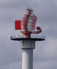
The SRE-M radar antenna combines two separate patterns, an upper cosecant-squared pattern and a lower pencil beam pattern to form a combined beam in the transmitting mode and a variable pattern in the receiving mode. Both patterns exhibit sharp bottom characteristics. In addition the cosecant-squared pattern features an upward lobe at the trailing edge to improve the signal-clutter ratio. Through the division of the output power to the two feds by correct phase, the shape of the antenna pattern is fixed to a definite relation. The polarization is vertical/circular swichable.
The received signals are fed to the receiver via a phase shifter and a variable power divider whitch may be digitally controlled in four steps. By appropriately setting the power divider, the original cosecant or pencil beam pattern as well as intermediate patterns may be produced.
The large horizontal array on the top of the antenna reflector, called the “Beacon”, this is the antenna of the Secondary Surveillance Radar (SSR). The SRE-M SSR-radar antenna is a Large Vertical Aperture (LVA antenna).
The SRE- M6 uses an up to eight-fold, the SRE- M7 an up to three-fold staggered pulse repetition frequency with a diversity frequency offset.
Due to the solid-state transmitter the SRE- M8 transmits pulses with different pulse duration:
| SRE - M6 /M7 | SRE- M8 | |
| Pulswidth | 2 µs | |
| Long range | up to 250 µs | |
| Short range | up to 12 µs | |
| Subpulse | 0,6 µs | |
| Pulse Power | > 2,5 MW | < 75 kW |
| PRF | 310 … 480 Hz | 300 … 700 Hz |

