Interferometric Radar
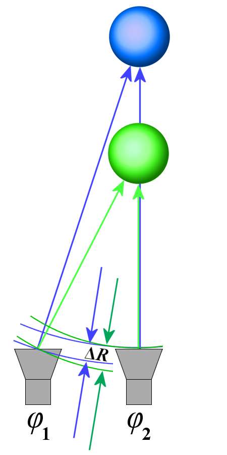
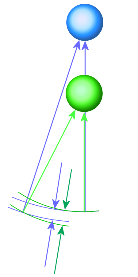
Figure 1: The phase difference ( φ1 − φ2 ) is a measure for the distance of the reflector.
Interferometric Radar
In radar technology, interferometry refers to all measurement methods in which a phase shift of the received signal is evaluated. Interferometric Synthetic Aperture Radar (InSAR) is an imaging radar technique, in which additional information is calculated by comparing the phases of two images resulting from different aspect angles.
The range resolution of radar sets is limited by their transmitter bandwidth. For radar sets with simple pulse modulation by the length of the transmitted pulse, for radar sets with intrapulse modulation by the bandwidth of the transmitted pulse. Direct measurement of the phase shift of the echo signal can be used for much more accurate distance measurement.
| φ = − | 4π·R | where | R = distance to reflector λ = wavelength of the transmitted signal |
(1) |
| λ |
Unfortunately, with such a measurement, the clear measuring distance is reduced to plus or minus half the wavelength of the carrier frequency by the cyclic function of the sinusoidal oscillation. The phase can be measured quite exactly in the range −π < φ ≤ +π, but it is not possible to determine how many full wavelengths are additionally allocated to this distance. With the InSAR, this deficiency can be remedied.
The basic structure is an arbitrary functional radar which is able to evaluate the phase information of the received echo signal. A coherent radar, which is able to generate a two-dimensional image by antenna swiveling, rotation or linear motion, is a mandatory prerequisite. The measured phase information is stored for each pixel. The entire process is repeated from a different antenna position. For each pixel of the image, the phase difference from both measurements is a measure for the distance difference ΔR and thus also for its distance (see Figure 1). Image processing now makes it possible to compare the two phase images with a measurement accuracy of up to a fraction of the wavelength. Here, too, ambiguities still arise but considerably less than with direct measurement. These ambiguities can be removed by comparing the result with neighboring pixels and evaluating the probability of a possible phase jump.
| ΔR = f(φ1 − φ2) | (2) |
The phase image of each individual measurement represents a chaotic mess that appears like a colored noise pattern. Finally, the phase difference of the two images results in evaluable distance information. There are simple trigonometric relationships between the phase difference and the real distance R. The distance between the two antenna positions (the so-called baseline) is a multiplier for the phase difference. The baseline should not be too large so that the reflection conditions between the two measurements do not change.
The InSAR was originally developed for remote sensing of the Earth using the Synthetic Aperture Radar. For example, during the Shuttle Radar Topography Mission (SRTM) in February 2000, a second receiving antenna was deployed on a 60 m long slidable lattice grate. So both aspects were created at the same time. In the tandem missions ERS-1 and ERS-2, both measurements were performed sequentially.
The process is also suitable for use on the ground. Here it is referred to as Ground Based Interferometric SAR (GBInSAR). With the GBInSAR, changes in the environment can be measured with millimeter accuracy, for example, glacier changes, landslides, volcanic activities, distortions after earthquakes and static monitoring of constructions.