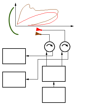
High- and Low- Beam

receiver
receiver
divider
Figure 2: Radar antenna with high- and low- beam pattern

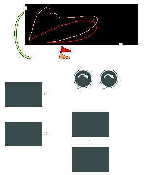
Figure 2: Radar antenna with high- and low- beam pattern
The Figure shows the power supply by two horn radiators. In practice, the horn radiator for the lower pattern (i.e. the upper one of the two) is supplied with more power than the one for the upper pattern. The transmitters power is split by a power splitter. Both horn radiators feed separate receiving channels to avoid interference.

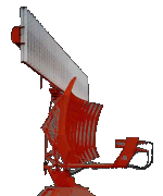
Figure 1: STAR-2000
with High- and Low-Beam- Feeding of the Antenna
It is also possible to feed only the radiator of the low-beam with the transmitter. This allows a greater range to be achieved at lower altitudes. Nevertheless, both channels are used for reception. This is possible because the diagram limits only show a level of −3 dB. With lower power components, however, both diagrams overlap almost completely. In the block diagram, the power divider and one of the duplexers will then be omitted. Since the high-beam radiator also receives some of the transmitter's energy directly from the low-beam radiator, the input of the receiver, which has no duplexer, must be protected with a limiter.
