V-Beam

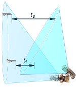
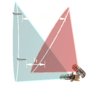
Figure 2: The pattern of the upper antenna is distorted from the horizontal one.

Figure 2: The pattern of the upper antenna is distorted from the horizontal one.
V-Beam
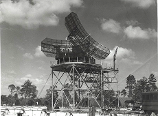
V-Beam is radar scan pattern modus in which separate radar transmitters feed two antennas which produce vertical fan beams. One antenna is tilted from the horizontal by approximately 30 degrees. This has the effect of displacing the resulting fan-shaped elevation beam by the same amount from the vertical. This beam, in combination with the vertical beam produced by the companion antenna, thus provides the means for height-finding by the V-beam technique. Target elevation is deduced by comparing the time differences in echo response experienced by the two antennas.


