Thermistor Bridge
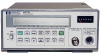
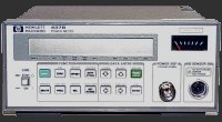
Figure 1: Powermeter HP 437 B
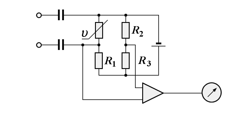
An RF-power meter is intended to measure high-frequency power independent of frequency as possible. For this purpose, a thermistor is inserted into a resistance measuring bridge. The normal bridge balance results in no indication at the measuring instrument (equivalent to: Power = 0).
Figure 2 is an example of a thermistor bridge used for rf power measurements. A thermistor bridge circuit includes other thermistor elements, referred to as compensating thermistors. These thermistors respond to fluctuations in ambient temperature so that the bridge balances and calibration are maintained over a wide temperature range. Compensating thermistors are usually in disc form so that they can be mounted on a flat.
instrument
Figure 2: Principle of a thermistor bridge
instrument
Figure 2: Principle of a thermistor bridge
The bolometer is a loading device that undergoes changes of resistance as changes in dissipated power occur. The thermistor decreases in resistance as the power increases. The resistance is measured before and after the application of rf power. If the same change in resistance is then produced by a variable dc source of power, then the rf power is equal to the measured dc power. This relationship makes possible the direct calibration of a bridge circuit in units of power. In other words, one condition of balance exists when no rf power is applied; but in the presence of power, a second condition of balance exists because of the resistance changes of the bolometer. It is this change of resistance that is calibrated in power.
Well, three conditions must be looked at:
- the permitted load of the thermistor (that is the piece of equipment)
- the permitted constant load of the bolometer
- the permitted impulse load of this bolometer.
Measurement range transgressions are then avoided by preconnected attenuators.
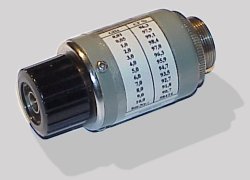
Figure 3: Bolometer HP 232 C
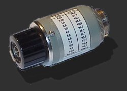
Figure 3: Bolometer HP 232 C
A bolometer features a specially constructed element of temperature-sensitive material. The active material is a semiconductor bead supported between two pigtail leads. When rf power is applied to a bolometer element, the power absorption by the element heats the element and causes a change in its electrical resistance. Thus, a bolometer can be used in a bridge circuit so that small resistance changes can be easily detected and power measurement can be accomplished by the substitution method (that is, substitution of dc or low-frequency power to produce an equivalent heating effect).

