Electrical Characteristics of Transmission Lines
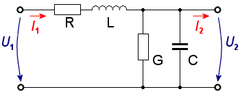
Figure 1: Transmission Line Element. Here we have C, L, G, and R as the capacitance, inductance, conductance, and resistance per unit length of transmission line
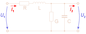
Figure 1: Transmission Line Element. Here we have C, L, G, and R as the capacitance, inductance, conductance, and resistance per unit length of transmission line
Electrical Characteristics of Transmission Lines
We can find electric conductors for the supply of various devices with electric energy everywhere. In communication electronics, in particular, cables have a further task than just transporting energy, such as transmitting messages over the phone. However, a message on a line does not reach the receiver unchanged over 100 km but is subject to many influences along the line, which affect the signal.
If one compares the output signal of a line with the input signal, one will notice changes which have the following causes:
- Distortions,
- Decrements or
- Run time differences at different frequencies.
Since each cable has different properties but all cables are subject to the same influences, an equivalent circuit diagram can be drawn for one cable, which is shown in Figure 1. An ohmic series resistor R, a line inductance L, an insulation value G, and a line capacitance C act on the transmission line.
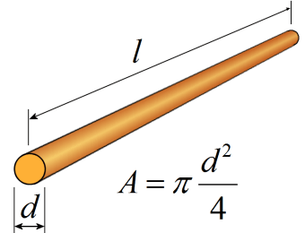
Figure 2: Calculation of the resistance of a round wire
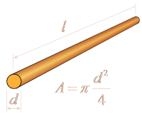
Figure 2: Calculation of the resistance of a round wire
Series Resistance R
Every conductor pits a resistance against the electric current since the mobile electrons always meet atom trunks and are braked, therefore.
With a formula the resistance can be described so:
| R = ρ· | l | in [Ω] | R = series resistance in [Ω] l = length of the conductor in [m] A = cross-sectional area of the conductor in [mm²] ρ = specific resistance in [Ω·mm²/m] |
(1) |
| A |
The characteristic quantity is indicated of e.g. 1 km and then described as specific series resistance R' in data sheets for a defined conductor length. The series resistance is calculated with the following formula:
| R' = | R | in | Ω | (2) |
| l | km |
Inductance L
A magnetic field builds itself up around any conductor current flowed through. The magnetic field changes proportionally to the calculated alternating voltage. Through this, a tension that counteracts her cause is induced in the conductor. This induced voltage weakens the current flux with that. The value of the inductor L depends on the following parameters:
- the length of the conductor,
- the cross-sectional area of the conductor and
- the separation between the wires.
The characteristic quantity is indicated of e.g. 1 km and then described as specific inductance per unit length L' in data sheets for a defined conductor length. The inductance per unit length is calculated with the following formula:
| L' = | L | in | mH | (3) |
| l | km |
Parallel Resistance G
In the practice, there isn't any ideal insulator which is without any electric current. A certain leak current that flows about the insulation between the two wires therefore always appears at an isolated two-wire line, too. The value of the conducting ability is marked by G and sometimes also is called cross-resistance or derivation. As a measurement unit for the conductance, the S (“Siemens”) is used.
| G = | 1 | in [S] | (4) |
| R |
The characteristic quantity is indicated of e.g. 1 km and then described as conductance G' in data sheets for a defined conductor length. The conductance is calculated with the following formula:
| G' = | G | in | S | (5) |
| l | km |
Parallel Capacity C
Every electric consumer has an inner resistance at which the voltage is exhausted. If this voltage is here led by conduction to the consumer, a different potential arises between the two wires.
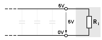
Figure 3: Rising of the parallel capacity
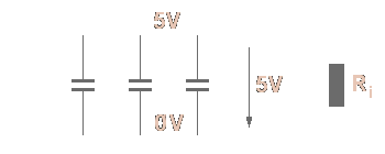
Figure 3: Rising of the parallel capacity
Therefore both wires work like the plates of a condenser. This coupling over the electric field is described with capacity C.
Capacitance C' is the measurement of energy absorbed by the cable. It is related to the inner and outer conductor sizes and the core dielectric constant. In a given cable design, capacitance and impedance are inversely proportional. The fewer the picofarad per foot, the better the cable performance. The characteristic quantity is indicated of (e.g. 1 km or 1 ft) and then described in data sheets for a defined conductor length. The capacitance is determined by the formula:
| C' = | C | in | nF | (6) |
| l | km |
Impedance
Characteristic impedance is a measurement of resistance to the electrical current being carried in a cable. It is measured in units called Ohms (Ω) and is directly related to the ratio between the inner conductor dimension and the outer conductor dimension, and inversely related to the dielectric constant of the cable core. Unlike conductor resistance, impedance does not vary with cable length.
For a system to work at maximum efficiency, the nominal impedance of the transmitter, receiver, and cable must precisely match. An incorrect match will produce reflection loss. Nominal impedance is determined by the formula:
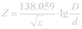
Where:
Z is the impedance of the cable
ε is the dielectric constant of the cable core
D is the dielectric diameter
d is the conductor diameter
