Waveguide Joints

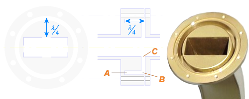
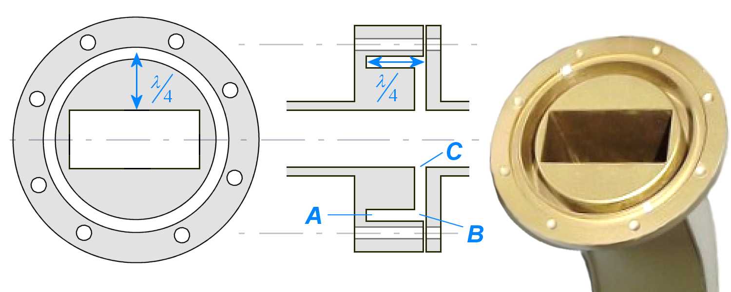
Figure 1: Choke joint

Figure 1: Choke joint
Waveguide Joints
Since an entire waveguide system cannot possibly be molded into one piece, the waveguide must be constructed in sections and the sections connected with joints. The three basic types of waveguide joints are:
- permanent joints
The permanent joint is a factory-welded joint that requires no maintenance. - semipermanent joints
Sections of waveguide must be taken apart for maintenance and repair. A semipermanent joint, called a “choke joint”, is most commonly used for this purpose. The choke joint provides good electromagnetic continuity between sections of waveguide with very little power loss. - rotating joints
Whenever a stationary rectangular waveguide is to be connected to a rotating antenna, a rotating joint must be used. A circular waveguide is normally used in a rotating joint. The rotating section of the joint also uses a choke joint to complete the electrical connection with the stationary section.
Choke Joint
Sections of waveguide must be taken apart for maintenance and repair. A semipermanent joint, called a „choke joint”, is most commonly used for this purpose. The choke joint provides good electromagnetic continuity between sections of waveguide with very little power loss.
A cross-sectional view of a choke joint is shown in the figure. The pressure gasket shown between the two metal surfaces forms an airtight seal.
Notice that the slot is exactly ¼ λ from the “a” wall of the waveguide.


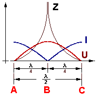
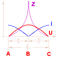
Figure 2: Transformation of the impedance
The slot is also ¼ λ deep, as shown, and because it is shorted at the end, a high impedance results after ¼ λ. The high impedance after ¼ λ results in a low impedance, or short, after ½λ.
This effect creates a good electrical connection between the two sections that permits energy to pass with very little reflection or loss. There is therefore a (HF) electrically conducting connection between the two waveguide sections. A galvanic connection of the two waveguide sections or the flanges isn't necessary at this. Therefore it is possible to mount a seal between the two flanges to lock the inside of the waveguide airtightly.
The expression “choke joint” for the described flange connection was chosen because of its effect like a HF choke. As when a HF choke the HF energy shall be prevented from the migration by the connecting piece to the outside.
