Antenna Beams for command guided missiles

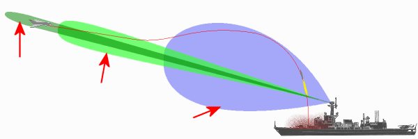
Figure 1: The path of the missile through the beams
In a radar system for command-guided missile guidance, several special antenna diagrams are formed. Command Guided is a missile guidance system in which a computer calculates control signals for the missile and transmits them to the missile to enable the missile to travel directly to the calculated point of impact. The radar thus consists of two systems: one or more target channels and one or more missile control channels.
Capture Beam / Guidance Beam
A wide beam incorporated in capture transmitters of beam rider (command guided) missile systems to facilitate gaining initial control of a missile immediately after launch. Upon capture, the system then centers the missile in the narrow guidance beam. The figure illustrates a launched missile at point of capture.
Track Beam
These are of two primary types: conical scan and monopulse.
- The conical scan system directs the radar signal in a circle around the target. The radar paints this circle 15 to 40 times per second. As the target moves out of the center of this circle, the radar develops aim error voltages and re-aims the antenna.
- The monopulse system directs four beams at the target simultaneously. The target is in the middle of the four beams. If the target is not in the center, the radar return develops an aim error voltage to re-aim the antenna beam.
