Two-Way beamwidth

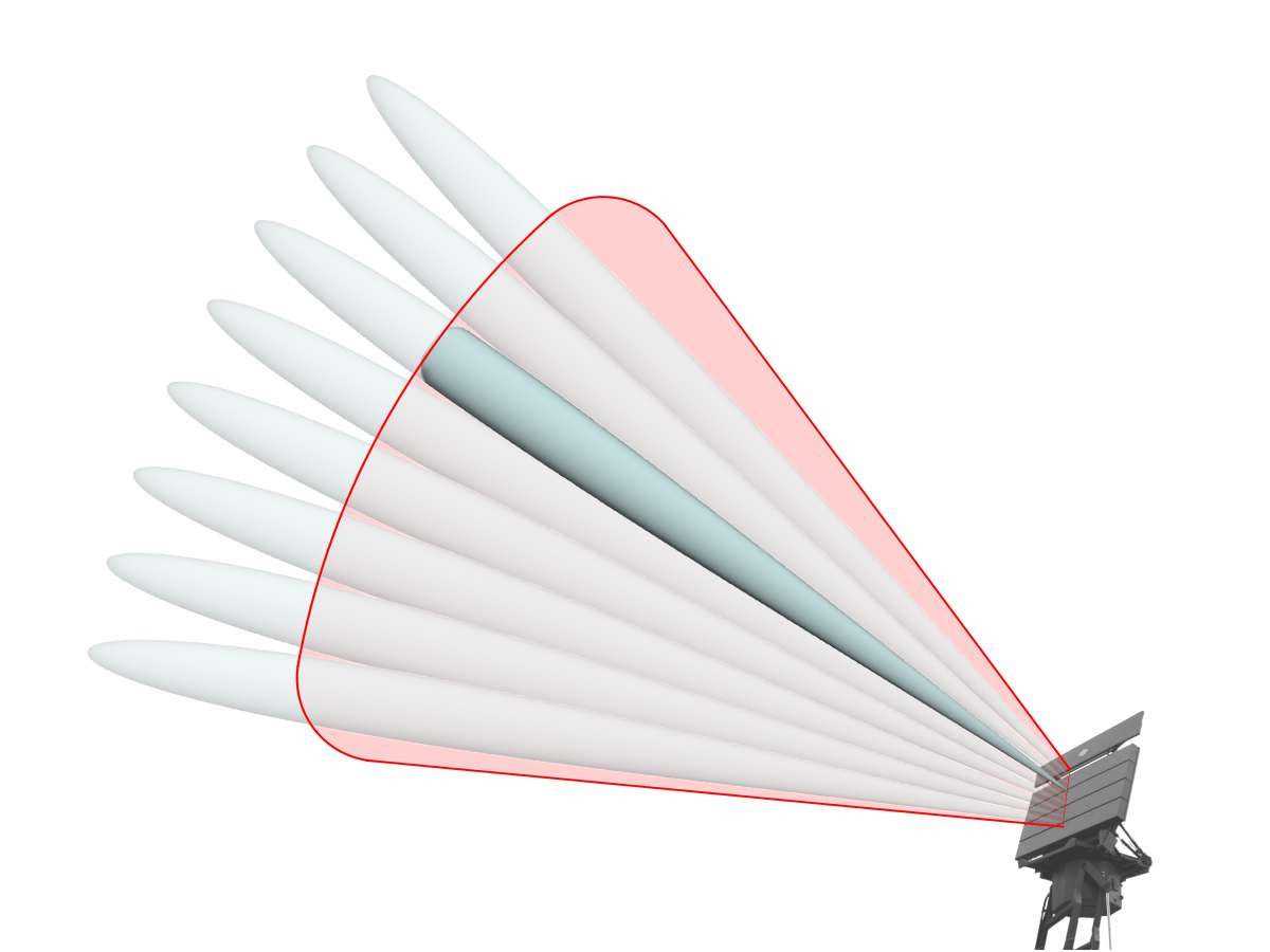
antenna pattern
narrow antenna patterns
during receiving time
of 6th receiver channel
Figure 1: Exemplary digitally shaped antenna pattern with Two-Way beamwidth

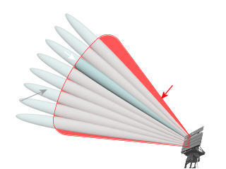
antenna pattern
narrow antenna patterns
during receiving time
of 6th receiver channel
Figure 1: Exemplary digitally shaped antenna pattern with Two-Way beamwidth
Two-Way beamwidth
A Two-Way beamwidth generally occurs when radar uses a different antenna pattern during transmitting time than during the receiving time. This is the case, for example, with multi-function radars using digital beamforming. Such radar must illuminate the entire room during the transmission time, for example, with a fan-beam pattern, which should then be searched during the receiving time by simultaneously formed single narrow pencil beams. But the radar receiver can only recognize this object, which is also illuminated by the transmit power. The superimposition of the transmitted antenna pattern with the effective antenna pattern during the receiving time is then a two-way antenna pattern with a given beamwidth.

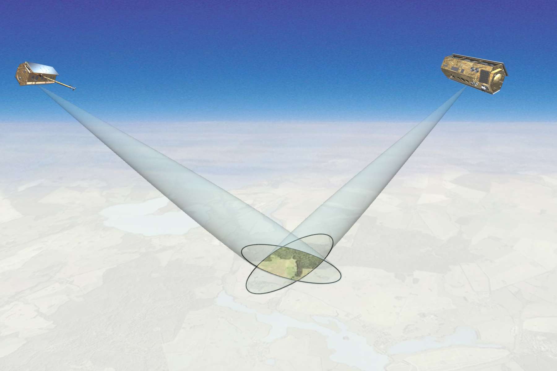
Figure 2: Two-way antenna diagram through different aspect angles
A second possibility for the arising of a two-way antenna diagram is the use of two identical antenna diagrams but from different aspect angles. A side-looking airborne radar generates, for example, a symmetrical (circular) antenna pattern. If this one symmetrical antenna diagram falls obliquely on the earth's surface, this results in an illuminated surface in the form of an ellipse. A second satellite from a different position carries the receiver and an antenna with the same antenna pattern and also targets this area. It also creates an ellipse but it's twisted relative to the first one. Only the area illuminated by both ellipses can be observed. In extreme cases, these ellipses are crossed one above the other. The usable beamwidth of these superimposed antenna patterns thus decreases approximately to the -1.5 dB power level.
In the case of a synthetic aperture radar, this case also arises, for example, in spotlight mode, since all received echo signals from different satellite positions must be used for signal processing. Only this part of the surface can be used to calculate the radar image from the synthetic aperture that the satellite can illuminate uniformly from different aspect angles. This also improves the cross-range resolution resulting from the smaller beamwidth of the two-way antenna diagram (-1.5 dB beamwidth instead of the -3 dB beamwidth).

