Schwarzschild-Horn

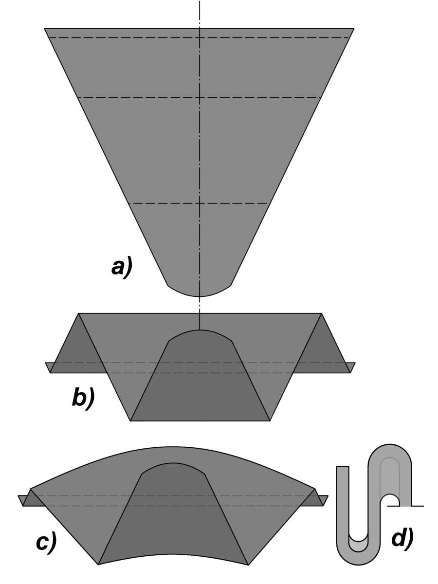
Figure 1: Successive steps imagined in folding the Schwarzschild-horn, die Faltstellen im Ergebnis haben den Querschnitt von Hohlleiter-Biegungen.

Figure 1: Successive steps imagined in folding the Schwarzschild-horn, the folds in the result have the cross-section of
waveguide-bends.
a) flat sheet metal;
b) folded;
c) cut and inserted reflectors;
d) side view of c).
Schwarzschild-Horn
The Schwarzschild-Horn system is a derivation of the Cassegrain antenna that improves the off-axis performance by satisfying the Abbé sine condition. The Schwarzschild type horn feed has a larger concave secondary reflector than the primary convex reflector, both inside the horn. Unlike the Cassegrain antenna, the reflector cross-sections are not simple conic sections but transcendental curves. For on-axis operation this antenna system offers no improvement over a Cassegrain antenna. However, for scanning a very narrow beam over a small physical angle its performance can be far superior than that of a Cassegrain antenna. The design of the reflector surfaces involves an elaborate computational procedure and is dependent upon the beamwidth and scan angle. The Schwarzschild-Horn is then fed e.g. by an Organ-Pipe Scanner.
Since the reflector surfaces are not simple conic sections, and the tolerance problem can be expected to be severe, this system has not found wide application. The only operational model built appears to be the antenna for the AN/MPG-1 radar set developed at the Radiation Laboratory during World War II and buildt by Bendix.
Schwarzschild Horn was named after the telescope that was developed in 1905 by the German astronomer Karl Schwarzschild (*1873 - †1916).
Sources:
- R. C. Hansen: ''Microwave Scanning Antennas. Volume 1: Apertures'' New York, New York; London, England: Academic Press, Inc., 1964, ISBN 9781483260631 S.123 (online preview)
- W. Cady et al. ''Antennas, Scanners, and Stabilization'' in L. de Ridenour et al: ''Radar System Engineering'' Mc Graw-Hill, New York, 1947, Chapter 9, p. 297
