Weighting
Figure 1: Four frequencies as part of a linear frequency modulation
Figure 1: Four frequencies as part of a linear frequency modulation
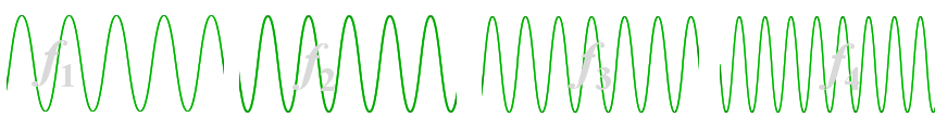
Figure 1: Four frequencies as part of a linear frequency modulation
If some different frequencies are added during the processing of pulse compression, then arise side lobes inevitably. These unwanted pulses are called “Time Side Lobes”.
In Figure 1 are shown four exemplary frequencies. These frequencies as part of a linear frequency modulated radar pulse (intrapulsemodulation) will be separated by filters, delayed and then added. This electronical solution can realized either with analog SAW filters or with digital wirings or even with a software.
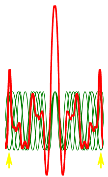
Figure 2: Sum of the magnitudes of the four frequencies
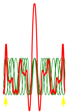
Figure 2: Sum of the magnitudes of the four frequencies
In Figure 2 you can see the sum of these four frequencies, if they are added without any weighting. This means all instantaneous voltages are added with the same amplification factor. The result is a sharp pulse in the center but some time side lobes beside the center in symmetric distances. Here the x-axis is the timeline - the pulses have got a different running time to the transmitted pulse, thus a different range therefore!
The yellow arrows points to a wave of a frequency (here this is the f2 frequency) having a voltage minimum directly opposed to this maximum of a time side lobe. If this f2 frequency will substain a higher amplification then the other frequencies, this time side lobe will be decreased. Of course: this will produce new side lobes at other positions but you can find an optimum of amplification factor for every frequency to achieve an optimized output signal with a minimum of side lobes.
The different amplification factor is called “Weighting”. With help of weighting you can get a suppression of the time side lobes up to -30 Decibels.