Clutter- Doppler Filter
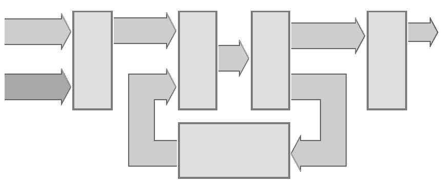
The I & Q output from the phase sensitive analog/digital converter (ADC) is fed to an arithmetic logic. Here the I & Q data are multiply by a weighting data. In the first period the memory is empty yet, all data are zero. The output of the arithmetic logic is stored in the memory. In the first period the output signal of the Adder is the data of the first period. The second period will be added to the stored in a memory predecessor (or the intermediary result). The constant clutter-signals of the tree pulse periods are added to the value zero, if the weighting signals of the three periods can be added to zero too. The pulsating signals of targets with a Doppler-frequency are added to a detectable value. Output signals can be generated during the third pulse period only.
(or I-data)
data
data
Figure 1: Block diagram of the Clutter Doppler Filter in a digital receiver, using the algorithm “Integrate & Dump”
(or I-data)
data
data
Figure 1: Block diagram of the Clutter Doppler Filter in a digital receiver, using the algorithm “Integrate & Dump”
data
data
Figure 1: Block diagram of the Clutter Doppler Filter in a digital receiver, using the algorithm “Integrate & Dump” (interactive picture)
The clutter Doppler filter “Integrate & Dump” works with three pulse periods often. This structure is open to compare more pulse periods too. The same hardware can be used to compare four pulse periods, if the software can provide this. The cycle must be enhanced and the weighting data adjusted only.
Description of the modules in the block diagram
The following example demonstrates the use of three-pulse method to calculate the output signal for a fixed target. The fixed target has always an identical phase and amplitude, are therefore the I&Q- data in the three-pulse periods are also approximately equal.
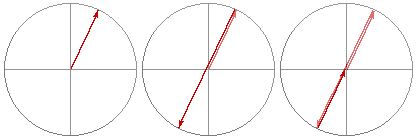
weighting = 1
weighting = -2
weighting = 1
Figure 2: Processing of the vectors of fixed clutter
weighting = 1
weighting = -2
weighting = 1
Figure 2: Processing of the vectors of fixed clutter
The output is as expected as a - 2·a + a = 0. Fixed clutter without Doppler frequency are thus suppressed. In the next example, the magnitude of the phase and amplitude are not equal between scan-to-scan. The weighted three input data are added up to those shown as green vector CDF data.
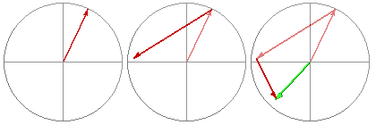
weighting = 1
weighting = -2
weighting = 1
Figure 2: Processing of the vectors of a moving target; the output vector (green) are CDF-Data
weighting = 1
weighting = -2
weighting = 1
Figure 2: Processing of the vectors of a moving target; the output vector (green) are CDF-Data