Directional Coupler
Figure 1: Principle of a coaxial directional coupler
Figure 1: Principle of a coaxial directional coupler
Directional Coupler
A directional coupler is a passive device which couples part of the transmission power by a known amount out through another port, often by using two transmission lines set close enough together such that energy passing through one is coupled to the other. As shown in Figure 1, the isolated port is terminated with an internal or external matched load (typically 50 ohms). Common properties desired for all directional couplers are wide operational bandwidth, high directivity, and a good impedance match at all ports when the other ports are terminated in matched loads.
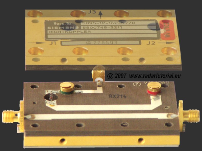
Depending on mounting direction this measuring loop receives a certain part of the ongoing or backcoming wave. The term main line refers to the mounting direction for measuring the ongoing wave.
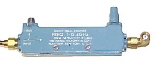
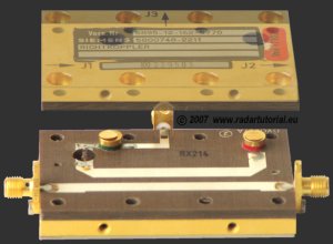
Figure 2: Directional Coupler
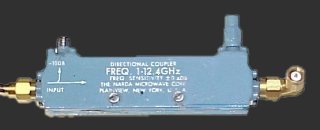
Figure 2: Directional Coupler
Any port can be the input, which will result in the directly connected port being the transmitted port, adjacent port being the coupled port, and the diagonal port being the isolated port. The coupled output from the directional coupler can be used to obtain the information on the signal without interrupting the main power flow in the system.
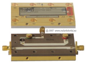
Figure 3: Directional Coupler in stripline-technology