Balanced Amplifier

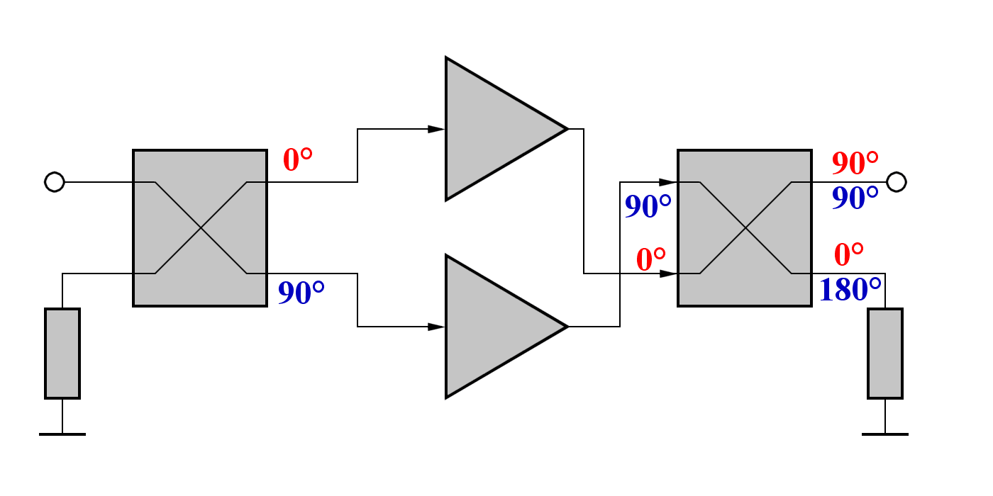
Figure 1: Principle of balanced amplifier

Figure 1: Principle of balanced amplifier
Balanced Amplifier
During the early years of using solid-state amplifiers in radar technology, the balanced amplifier approach was most widely used. Each amplifier stage in a balanced design employs 90° hybrids at the input and output to feed two discrete transistor stages. These devices are special configuration of directional couplers (sometimes called to as –3 dB coupler or hybrid coupler or “quadrature coupler,” or a –3 dB hybrid coupler amongst other names. This coupler has the characteristics of dividing the input power into two paths the have equal powers when terminated properly. The phasing between the both output ports of the hybrid is 90 degrees. At the output hybrid, these two paths with a phase difference of 90° get an additional phase shift. They are added at one port (using constructive interference), and suppressed at the other port (destructive interference).
This type of design of amplifiers have following advantages:
- good impedance matching characteristics;
- easily cascadable stages;
- easy power matching;
- improved output power performance.
The disadvantages of this type of design are:
- the adversely affected cost and size of the modules (because there are a doubled number of transistors per stage);
- the loss of the 90° hybrid will degrade the minimum achievable noise figure;
- the limited bandwidth (due to the problems in realizing multioctave 90° hybrids).
