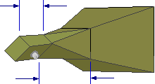
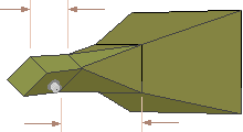
Circular Polorization with Horn Feeds
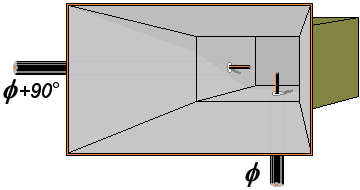
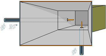
Figure 1: Circular polarisation by dual feeding
Circular polarization in a horn is created with a quadrature hybrid causing 90 degree phase difference between signal components before signal is applied to horn. Signal is injected by means of separate probes in space quadrature.
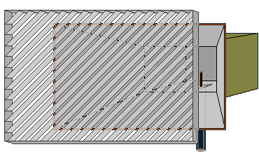
Figure 2: Layered polarizer
Passing a linearly polarized signal through a layered polarizer can achieve circular polarization. The polarizer is inclined at 45° so that one component of signal passes through unhindered while the other component undergoes propagation delay.
This method of changig the polarization is used by some Cassegrain- antennae.
Coax to waveguide |
Figure 3: Changing of polarization in a waveguide
Another method for circular polarization in horn antennas is achieved by injecting the input at a 45° angle to the horn's orientation. A combination of methods is then used to delay the selected orthogonal component.
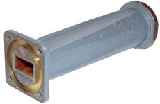
Figure 4: transition from a waveguide with rectangle cross-cut to a round waveguide feeding a Scalar Horn
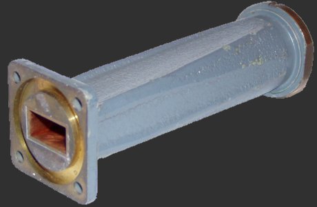
Figure 4: transition from a waveguide with rectangle cross-cut to a round waveguide feeding a
Scalar Horn

