Corner reflectors or Radar reflectors

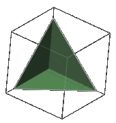
Figure 1: Triangular corner reflector as a cutout of a hollow cube
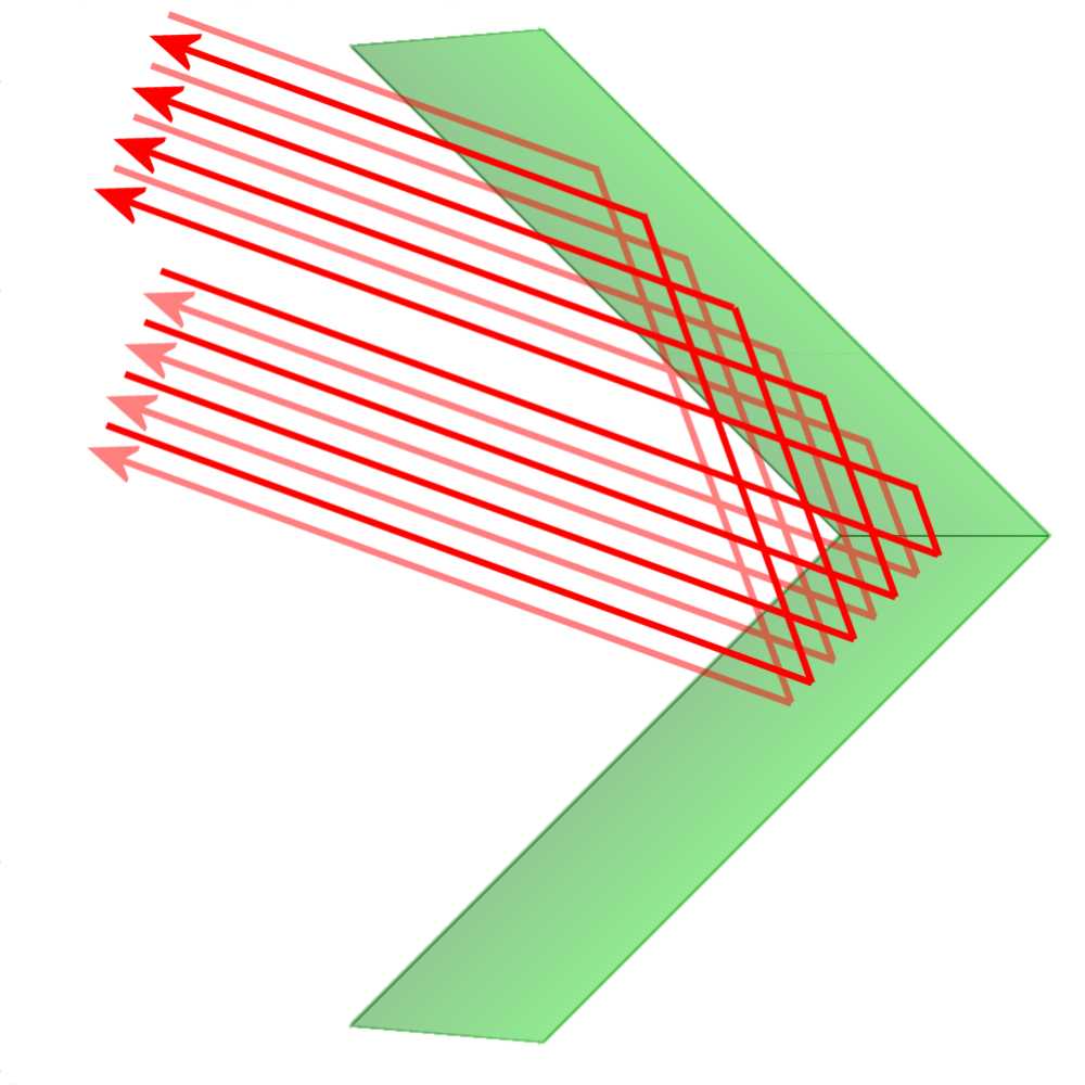
Figure 2: Reflection on two surfaces standing perpendicular to each other
Corner reflectors are used to generate a particularly strong radar echo from objects that would otherwise have only very low effective Radar cross-section (RCS). A corner reflector consisting of two or three electrically conductive surfaces which are mounted crosswise (at an angle of exactly 90 degrees). Incoming electromagnetic waves are backscattered by multiple reflection accurately in that direction from which they come. Thus, even small objects with small RCS yield a sufficiently strong echo.
The single areas of the corner reflector should be large compared to the radar wavelength. The larger a corner reflector is, the more energy is reflected. It can also be constructed in resonance with the radar wavelength. This will increase the echo signals again. To reduce losses caused by the earth's curvature the corner-reflectors are mounted as high as possible at the top of a mast at small boats. If too much wind load would disturb, then spherical or cylindrical disguised versions are used.
If should be backscattered in a three-dimensional directions, the corner reflector must be constructed of three reflecting surfaces. If should be backscattered in three-dimensionally distributed directions, then the corner reflector must be made of three reflecting areas. It is then called trihedral corner reflector. It will take place three reflections then before the beam is reflected back in the original direction.
Calculation of corner reflectors
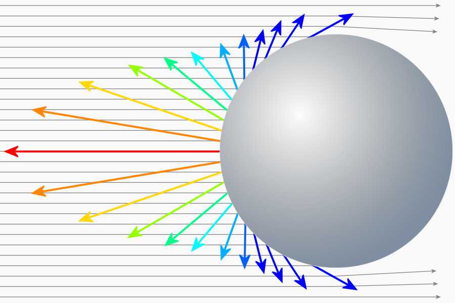
Figure 3: The reference for the RCS is a metallic sphere, which provides a (projected) circular area with a size of 1 m2 in the view.
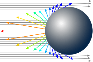
Figure 3: The reference for the RCS is a metallic sphere, which provides a (projected) circular area with a size of 1 m2 in the view.

Figure 4: Dependence of the effective surface visible from the angle of incidence of the radar
The specification of an area based on a comparison with an isotropic radiator. Here an ideal spherical conductor is assumed as the reference reflector whose graphical projection onto a plane perpendicular to the direction of the incoming rays (read: its shadow on this plane) has an area of one square meter. These circular area has a diameter of about 1.33 m. From this reference reflector, only a very small area is effective. As a reflector acts a small area (few centimeters only) in the middle of the sphere, which reflect the incoming energy in the direction of the radar exactly. All other subareas distribute the incoming energy evenly throughout the room. It follows that a small handy corner reflector with only a few centimeters of geometric spread can have an effective radar cross-section of several square meters. Here one must know that this number of example given 12 m2 actually only says that this little corner reflector reflects the same energy, as 12 spheres per one square meter!
Such a sphere will, as it is independent of the direction, generating a return signal even at a bistatic radar. A corner reflector cannot do that. The corner reflector concentrates the energy that is scattered at a sphere in almost all directions, only in exactly one direction: back to the radar. Therefore, a corner reflector has got an RCS, which is very much larger than its geometrical dimensions.
In the calculation of corner reflectors three aspects must be considered. The radar cross-section is dependent on:
- the frequency-independent calculated viewable area,
- the angle of incidence of the radar, and
- possible resonances at certain frequencies.
Visible surface
If (initially), it is assumed that the edge lengths of the corner reflector is substantially larger than the wavelength, the calculation of the effective area can be made according to the laws of geometrical optics. Thus, the basis for calculating is a projection of the corner reflector areas to a plane perpendicular to the radar radiation. In Figure 4 this is the segment AB. One can imagine this as a (radar) shadow of the corner reflector located on an imaginary plane perpendicular to the radar beam. This äqivalent surface (only computationally existing) is greatest when the radiation hit parallel to the plane of symmetry, ie at an angle of exactly 45 degrees on all subareas of the corner reflector.
An exception occurs when the radiation is incident exactly perpendicular to one of the subareas of the corner reflector. Then this acts with its entire surface as a planar mirror. Therefore, hereinafter referred formula derived is restricted to the condition that the incident radiation may only deviate less than 45 degrees from the line of symmetry (“boresight”).
In this case, the length of the “shadow” is a side of an isosceles triangle with side length of the corner reflector as the hypotenuse. The size of the area is then:
| Aproj = AWR· 20,5 | where | AWR = the area of only one side of the corner reflector Aproj = its projection, ie its “shadow” |
(1) |
From the table on the page with the explanation of the Radar cross-section we know the formula for the calculation of the RCS of a flat plate. This is derived from the calculation of the free-space loss, assuming that a rectangular plate is a small segment of a spherical surface:
| σ = | 4·π·A2 | mit | A = Surface of a mirroring plate λ = wavelength of scanning Radar |
(2) |
| λ2 |
This formula can be used generally for this to calculate the effective reflective surface, when the effective area of the corner reflector is known (see example given). The following versions of this formula have only one extension: to replace the surface formed by parallel projection Aproj with real measurable areas or sections, such as an edge length. We use the formula (1) into the formula (2) and get:
| σ = | 4·π·(AWR · 20,5)2 | = | 8·π·(AWR)2 | where | AWR = Surface of a mirroring plate λ = wavelength of scanning Radar |
(3) |
| λ2 | λ2 |
This formula applies to dihedral corner reflectors and when the faces are illuminated from the main direction (“boresight”) by radar set. The indication of wavelength in this formula is still no resonance, but is a consequence of the fact that into the derivation of the formula for the free-space loss is incorporated a virtual antenna gain (more precisely, the aperture of the receiving antenna). Sailors can use about 3 cm for the wavelength, since most of the maritime radar systems operate at about 10 GHz.
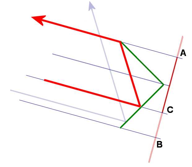
Figure 5: The area of the projection is reduced to a side length of segment AC
Angle of incidence
The “shadows” of the individual subareas are no longer at the same size for beams that have a different incoming angle than 45 degrees. Only the smaller projection of the corner reflector can reflect effectively, as shown in Figure 5 as the red ray. The larger projected subarea of the corner reflector but can only reflect the energy again, which is also mirrored by the first, smaller projected subarea. The other The incident energy that hits the remaining surface (marked with segment BC) is mirrored only once and then radiated into a different angle (as shown with the blue ray). This is a direction in which the reflected energy may not reach the receiver of a monostatic radar. The total effective usable graphical projected area can be only twice as large as the smaller graphical projected area. For angles 0° < Θ < 90° the effective dimensions of the effective area is:
| Aäquiv = smaller sub-surface + part of the larger sub-area | (4) |
| Aäquiv = AWR·sin Θ + AWR·tan Θ ·cos Θ = 2 AWR·sin Θ |
| σ = | 8·π·(AWR)2 | ·sin2 Θ | (5) |
| λ2 |
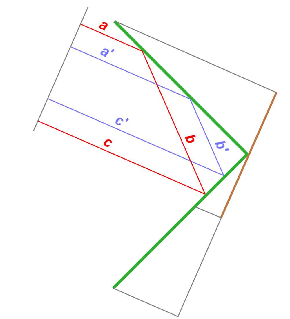
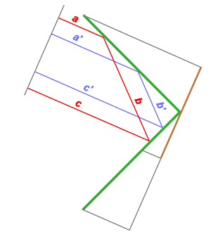
Figure 6: Same phase shifts due to the same length of the routes: a+b+c = a'+b'+c'
Influence of resonance
The concept that the metal surface function for electromagnetic waves like a mirror, is only a simplification. Really the metal surface receives the energy, thus oscillates itself and radiates the energy from again. A directional effect is caused by interference of partial energies with phase differences of the oscillations on different subareas. These phase differences are caused by the runtime differences of the incident radiation field to the different subareas. The currents which are induced in a single metal plate through this field, produce a very weak echo signal in the radar receiver, because many side lobes spread the energy of the secondary radiation. Only when both of these metal plates are arranged perpendicular, then the currents generate a more intense field of the secondary radiation, which is in phase in the direction of incidence of the radiation.
Similar to chaff the reflective surfacecan get a resonance with wavelength. The reflecting surface must be at least half the wavelength in the polarizing direction. But! It must involve at least two reflecting surfaces, ie the smallest resonant length of the corner reflector is a whole wavelength.
By the resonance in the width of the corner reflector of lambda can be measured up to four times the RCS, as one might guess geometrical dimensions. The reflector can also be excited by harmonics. The gain by the resonance but decreases by half with each higher harmonic. From ten times the wavelength no influence is observed. A negative impact has the resonance behavior but also: at odd multiples of half the wavelength (1,5λ, 2,5λ …) a reduction of the RCS can be observed by the same factors.
Trihedral corner reflectors
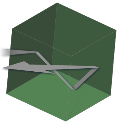
Figure 7: Corner reflector composed of three square faces

Figure 7: Corner reflector composed of three square faces
Because of the dihedral corner reflector no longer backscatter by a deviation of the incident beams from the normal to the edge plane in the direction of the radar device, are used usually corner reflectors with three subareas. These are known in geometry as trihedral corner reflectors.
Trihedraler Winkelreflektor aus quadratischen Blechen
These corner reflectors consisting of three square plates, which are welded to each at an angle of 90 degrees. The geometrically projected area thus now consists of three subareas, each is calculated by the formula (1) also. Merely this formula must now be applied twice per area (due to double reflection), but the result can be multiplied with three (there are three partial pathes).
| σ = | 12·π·(AWR)2 | ·sin2 Θ | (6) |
| λ2 |
Also, this formula is only valid for trihedral corner reflectors and when they are illuminated by radar from the direction of the symmetry axis (“boresight”). Thus, it is the maximum value that can be achieved. Practically this calculated here special case occurs very rarely. In most cases occurs much less RCS because the indident rays comes fron another angle then the “boresight”.
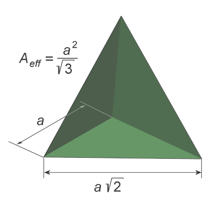
Figure 8: Corner reflector composed of three triangular surfaces

Figure 8: Corner reflector composed of three triangular surfaces
Trihedral, triangular corner reflector (made from triangular plates)
A corner reflector with three square faces is mechanically relatively unstable. Mostly therefore the partially surfaces are reduced to triangular faces (as shown in Figure 1 and Figure 8). Thus, the effective reflecting surface substantially reduced. An angular reflector for triangular faces having a larger beamwidth. The effective radar cross-section for this triangular corner reflector calculated by:
| σ = | 4·π·a4 | where | a = Length of the side edges of the three isosceles triangles λ = wavelength of scanning Radar |
(7) |
| 3·λ2 |
Such a corner reflector has an opening angle of almost 40 degrees, before the reflected power falls below the known from the antenna pattern -3dB limits. Therefore, up to eight such corner reflectors are assembled to form a cube. Now in each direction at least one reflector is effective.
This angle reflector is drawing from 12 isosceles triangles. But in practical construction are used three square plates with equal size (neglecting the plate thickness). One of these sheets will be diagonally halved and a second one quartered. The corner reflector is then welded together symmetrically from these seven parts. This self-built corner reflector with an edge length of the square sheets of 0,5 m then has got in the I/J-band an effective radar cross-section of far more than the five hundred times the value that would have a small rowing boat without this angle reflector. In inland navigation this small rowing boat is then a no longer be overlooked target mark on the radar screen!


