Active Radar Calibrator

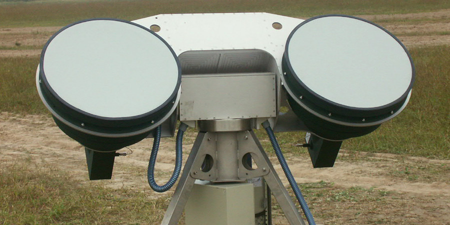
Figure 1: Active Radar Calibrator for L-Band
Active Radar Calibrator

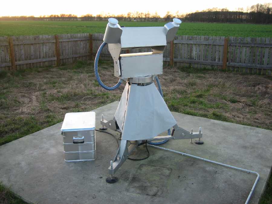
Figure 2: Active Radar Calibrator for X-Band
Active Radar Calibrators (ARCs) for Synthetic Aperture Radar (SAR) are transceivers at ground level, working like a transponder for secondary radar. An ARC points exactly in the direction of the satellite position on its orbit during the overflight. Such an overflight takes about 8 seconds. Meanwhile, the antenna of the ARC follows it. Beyond the time of overflights, the ARC enters a standby mode and turns the antennas in a more protected position. The ARCs receive the transmission signal of the satellite-based radar and measure its intensity. They reply on the same frequency with a precisely known (calibrated) transmission power. Since this active sent out signal is much greater than the passive reflected echo signals from the surroundings, generates this response signal in the satellite image a very bright point.
The antenna patterns of the scalar horn antennas of the ARC are well known. During an overflight, the amplitudes of the received signals are measured and stored into a memory. Thus, the antenna pattern can be measured in flight direction (along track, see SLAR Geometry). By constant uniform power of the responses may be measured the antenna pattern during the receiving time too.
Advanced modulation techniques in generating of the response signal allow to distinguish the response signal from the passive reflected echo signals of the surroundings. Thus, the bright spot can be recognized and removed from the satellite image. For this purpose, for example can be used a pulse-to-pulse Binary Phase Shift Keying (BPSK). If this code is known to the image processing software in the satellite, then the transponder response can be separated from the passive echo signals.

antenna
antenna
receiver
transmitter
divider
mixer
formation
to bipolar
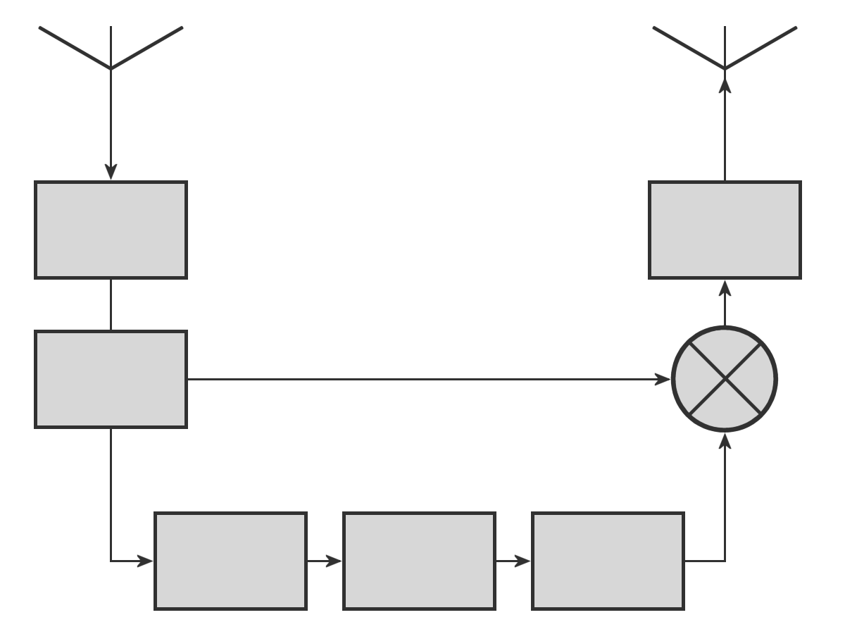
Figure 3: Block diagram of an ARC

antenna
antenna
receiver
transmitter
divider
mixer
formation
to bipolar
Figure 3: Block diagram of an ARC

antenna
antenna
receiver
transmitter
divider
mixer
formation
to bipolar
Figure 3: Block diagram of an ARC
In the receiver, the signal received by the receiving antenna radar signal is only amplified (not downconverted). The power divider distributes the RF energy to a balanced mixer and the clock formation. This is really just a counting circuit and tells the encoder, which radar pulse is expected next. The level converter sets depending on the current counter value and the corresponding current bit of code a positive or negative DC voltage to the mixer. The original carrier frequency of the radar is dependent phase-keyed by the polarity of this DC voltage. Each transponder response thus gets a code-dependent phase shift. The output signal is only amplified in the transmitter and radiated by the transmitting antenna.
Any internal runtimes or delays in the transponder would simulate a location below the earth's surface in a time-domain measurement. But SAR don't determine the distance with transit time measurements. Much more accurate is the use of the history of the Doppler-frequencies. Imposed on the way to the earth surface Doppler frequency is not affected by the direct reradiation of the received carrier frequency. The transponders reply gets the same Doppler shift as the passive echo signals of its environment. Therefore, a possible short internal delay time has no effect.
Coded ARCs have been used for the calibration of the C-Band radar satellites ERS 1/ERS 2.
