Common Requirements on Airborne Radars
Modern airborne radars are multimode radars mostly. The following figure shows the common requirements of various airborne radars:

Figure 1: Modes of operation of airborne radars
Figure 1: Modes of operation of airborne radars

Figure 1: Modes of operation of airborne radars
Non-imaging sensors take measurements in one linear dimension (like ground ranging), as opposed to the twodimensional representation of imaging sensors:
Radar antennas on aircraft are usually mounted on the underside of the platform so as to direct their beam to the side of the airplane in a direction normal to the flight path. For aircraft, this mode of operation is implied in the acronym SLAR, for Side Looking Airborne Radar. A real aperture SLAR system operates with a long antenna, usually shaped as a section of a cylinder wall. This radar type produces a beam of noncoherent pulses and uses its length to obtain the desired resolution (related to angular beamwidth) in the azimuthal (flight line) direction. At any instant the transmitted beam propagates outward within a fan-shaped plane, perpendicular to the flight line.
A second type of system, Synthetic Aperture Radar (SAR), is exclusive to moving platforms, such as aircrafts and satellites. An important characteristic of a SAR image is its resolution, which is defined in terms of minimum distance at which two closely spaced scatterers of equal strength may be resolved. SAR and conventional radar achieve slant range resolution in a similar way by using pulse-ranging technique. It uses an antenna of much smaller physical dimensions, which sends its pulses from different positions as the platform advances, simulating a real aperture by integrating the pulse echos into a composite signal. It is possible through appropriate processing to simulate effective antenna lengths up to 100 m or more. This system depends on the Doppler effect (apparent frequency shift due to the target’s or the radar-vehicle’s velocity) to determine azimuthal resolution. As coherent pulses transmitted from the radar source reflect from the ground to the advancing platform (aircraft or spacecraft), the target acts as if it were in apparent (relative) motion. This motion results in changing frequencies, which give rise to variations in phase and amplitude in the returned pulses. The radar records these data for later processing by digital correlation methods. The system analyzes the moderated pulses and recombines them to synthesize signals equivalent to those from a narrow-beam, real-aperture system.
Radar to operate in multiple modes using different (low, medium & high) pulse repetition frequency (PRF) and different waveforms.
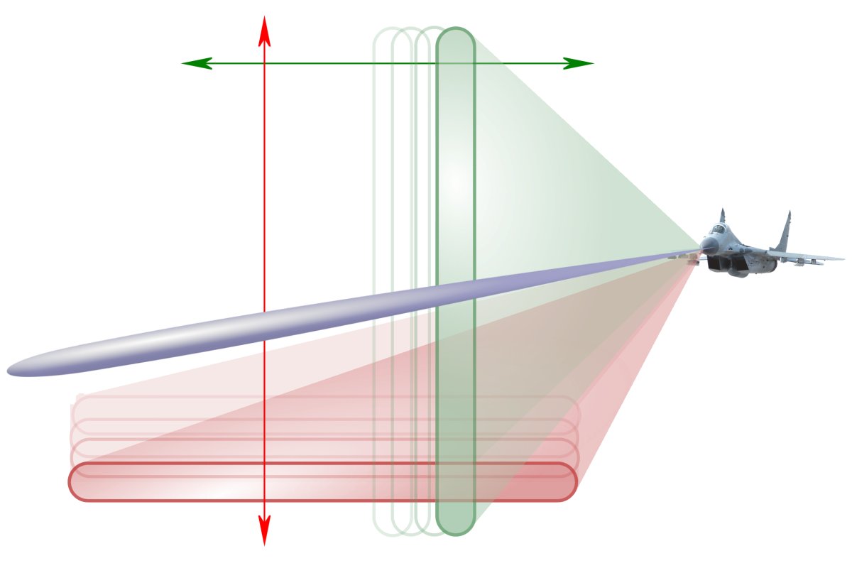
Figure 1: “Track while Scan”: The space is scanned alternately with two back and forth or up and down pivoting fan beams and a narrow pencil beam for tracking.
Figure 1: “Track while Scan”: The space is scanned alternately with two back and forth or up and down pivoting fan beams and a narrow pencil beam for tracking.
Detection and Tracking
This mode is specifically designed for detection and tracking of pointlike targets (such as aircrafts). Mostly this mode is implemented in a nose radar. This one must be suitable for a multi-mode operation. The radar uses a general search mode with fast pivoting beams. In rapid succession it also uses alternately a special tracking mode. In search mode, the antenna pattern is swept over the area to be searched. It may be temporarily waived even on an elevation angle or bearing angle measurement. The phased array forms a horizontally oriented up and down nodding fan beam. In tracking mode, it transmits a very narrow beam (“Pencil Beam”) exactly in the direction of the desired target. The radar transmits a number of pulses toward the target to increase the probability of detection here (see pulse integration). This mode is also-called “rack while scan” (TWS). Depending on the processing power of the radar signal processor for up to 30 targets can be tracked in the detection area. In contrast, in the mode “Single Target Track” (STT) is directed all transmission energy and processing power on a single target. This increases the maximum range and the probability of detection and enables more accurate target identification by the radar signal processor.
The transmitters waveform and the duration of the pulse period are each time adapted to the energetic limit of maximum range according to radar range equation and on the time budget of the radar. The aim is the reconnaissance of largest possible space, as well as for unambiguous measurement results according to the conditions of the Doppler dilemma. That means, the pulse repetition frequency may be varied during target tracking. Either to use a low pulse repetition frequency to achieve as large as possible unambiguous maximum range (mode “Range while Search”). A velocity measurement is omitted here. Or to use a high pulse repetition frequency to achieve as large as possible unambiguous speed measurement (“Velocity Search”), with waiving of the of now ambiguous range measuring.
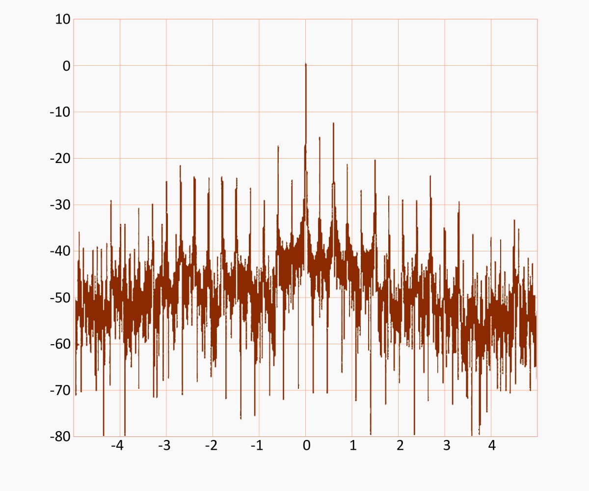
Figure 2: JEM spectrum of compressor blades of a jet engine, which was rotated here manually for measurement purposes
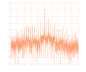
Figure 2: JEM spectrum of compressor blades of a jet engine, which was rotated here manually for measurement purposes
Raid Assessment
Another important radar feature, which is exploited an a designated target, is the “Raid Assessment” (ie., the assessment if the signal received during the time on target is relevant to a single or to multiple targets). This function is performed by illuminating the target with a wideband waveform and by trying to resolve in range the target cluster. This function is better exploited when the target is under track (in “Single Target Track”) since the extended dwell time allows a pulse integration of the returns from the individual scatterers.
So as the spectrum of the echo signal is changed and it is suspected a second reflective object therefore (or it is detected directly), can be expected with the launch of a missile.
Discrimination between fixed and rotary wing targets is done by analyzing the Doppler spectrum of the received echoes which, in rase of rotary wing targets, present some peculiar features depending on the number of rotors, on the number of blades, and an their rotation rate. The fixed wing target spectrum is far more narrow and may present peculiar lines (called JEM lines) related to the number of turbine blades and to their speed. These peculiarities of the target spectrum can be exploited not only to simply discriminate between the two above classes of targets but also to classify and identify a particular type of aircraft.
Depending on the aspect angle and following the different radial speed each compressor blade in the jet engine causes a different Doppler frequency. Its amplitude is very small, especially caused by the small size of these reflective objects. The process is therefore also-called “micro-Doppler” (m-D) effect. In the spectrum these m-D frequencies may appear as additional small lines left and right of the main Doppler frequency (caused by the radial velocity of the entire flying object). These frequency marks are then called JEM lines (“Jet Engine Modulation”).
Ground Ranging
Ground Ranging is usually a non-imaging radar technique. It is a mode of operation which is required for low-flying characteristics. It is also-called “terrain-following radar” and allows automatic fallback in the altitude when floor obstructions form the risk of a collision.
Contrary to the commonly encountered vision that here would be measured the height or altitude only, this radar must be directed forward to have enough time to avoid a collision. A simple altimeter is not suitable for this task.
Mapping Operations
In this method, the reflections on the floor are used in the sum to generate a map-like representation of the surrounding. It can be applied both in nose radars as well as in side looking airborne radars (SLAR). It is the main mode in the remote sensing of the Earth. Moving pointlike targets such as aircraft, cars, ships and railways are likely seen as clutter, as it occurs an additional Doppler frequency in respect to the movement of the radar platform. This causes problems with displaying of the correct range display often.
