Torus Antenna

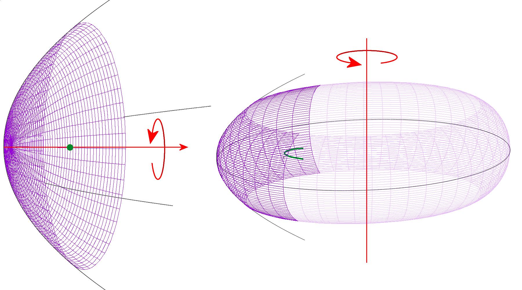
Figure 1: Wire frame of paraboloidal surfaces of revolution, left for a parabolic antenna, right for a torus antenna.

Figure 1: Wire frame of paraboloidal surfaces of revolution, left for a parabolic antenna, right for a torus antenna.
Torus Antenna
A torus antenna is based on the geometry of a surface of revolution of a parabola, as like as parabolic antenna. The reflectors of these antennas are cut outs of the respective surfaces of revolution. For the construction of a normal parabolic antenna parabola rotates about its axis of symmetry (see Figure 1, left). The rotating parabolic forms a circular paraboloid of revolution. In parabolic antennas, the symmetry axis of the parabola is the boresight of the antenna normally (i.e.: if the primary antenna is located at the focal point).
For torus antenna the axis of rotation is perpendicular to the symmetry axis of the parabola. The distance between the axis of rotation and the rotating surface must be larger than the focus of the parabola (see Figure 1, right). The torus antenna doesn't form a focal point but a group of focal lines, which lie on an arc in front of the reflector.
Compared to a parabolic antenna the torus antenna has larger aberration losses, because the primary antenna (for example, a feed horn) is not located at a focal point but only on a focal line. In case of receiving a part of the bundled by the reflector energy would not achieve the primary antenna. In addition, the primary antenna can illuminate only a limited area of the reflector. The antenna aperture is thus always substantially smaller than in a parabolic reflector.
In order to reduce this aberration losses a second reflector can be added similar to a Cassegrain antenna. With help of this socondary reflector the phase differences can be compensated at the boundaries of footprints on the primary reflector.

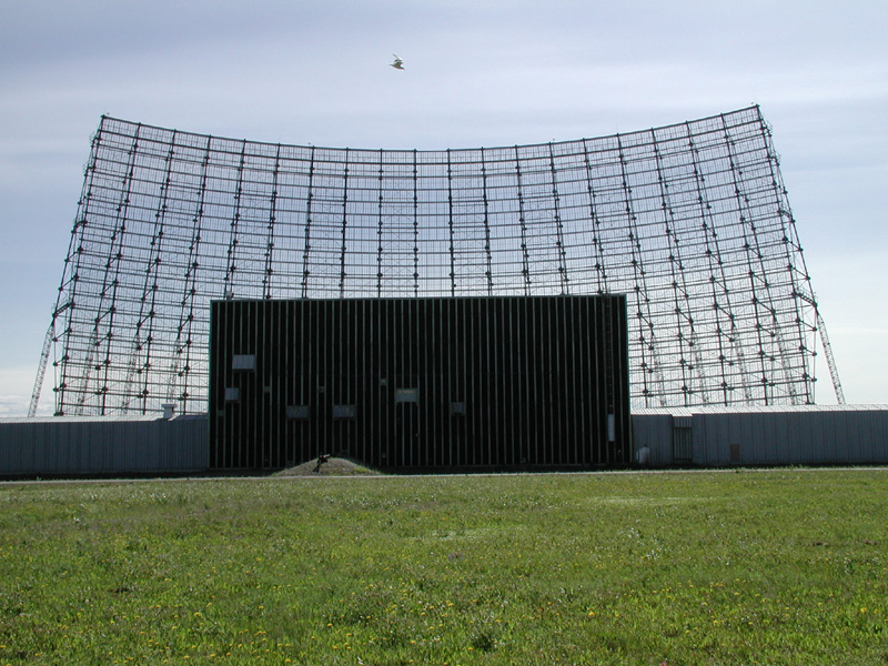
Figure 2: AN/FPS-50, DR3: a parabolic-torus antenna with an organ-pipe-scanner feed at Clear AFS, © 2000-2016 GlobalSecurity.org

Figure 2: AN/FPS-50, DR3: a parabolic-torus antenna with an organ-pipe-scanner feed at Clear
AFS,
© 2000-2016 GlobalSecurity.org
Torus antennas are used to allow a plurality of main beam directions simultaneously using only one large stationary reflector. This concept is used e.g. in OTH-B Radar because it's antenna reflectors (having extremely low resonant frequencies) are too large for a mechanical rotation. The parabolic-torus antenna reflector of an AN/FPS-50 radar was approximately the size of a football field. The feeding of this antenna was carried out with a so-called Organ-Pipe Scanner. This one switches alternately the radiators, which are arranged at different positions into the transmit/receive path. In this manner the antenna pattern is pivoted by selecting the feeding point in spite of a fixed reflector.
Sources and ressorces:
- Yahya Rahmat-Samii, Reflector Antenna Developments: A Perspective on the Past, Present and Future, 2015, IEEE Antennas and Propagation Magazine, Band 57, Ausgabe 2, ISSN 1045-9243, S. 85-95
