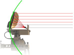
The Offset- Feed
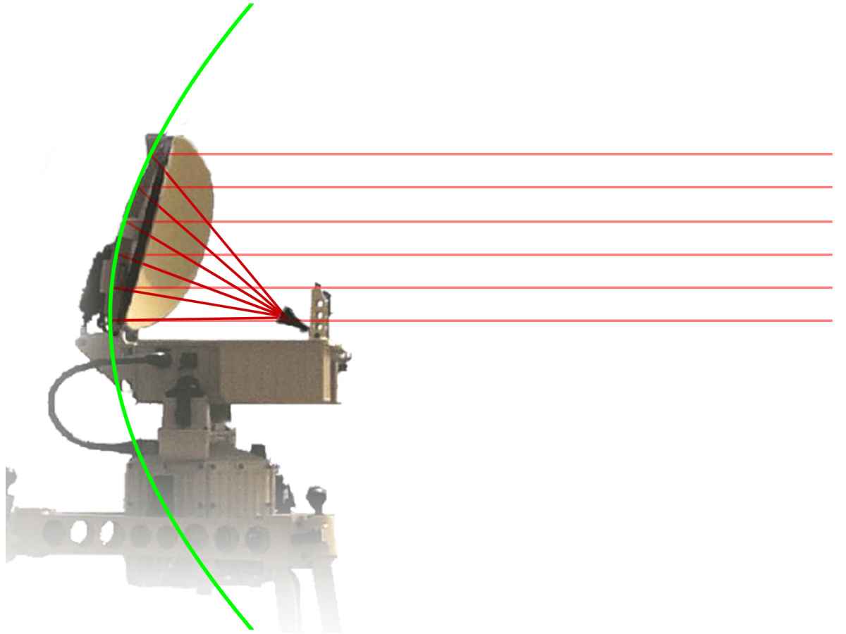
Figure 1: The offset antenna is a section of a paraboloid
The Offset- Feed
One problem associated with feedhorns is the shadow introduced by the feedhorn if it is in the path of the beam. The shadow is a dead spot directly in front of the feedhorn.Normally the feed horn constitutes an obstruction for the rays coming from the reflector at a parabolic antenna.
To solve this problem the feedhorn can be offset from center. In an offset feed, the feed is outside the path of the wave so there is no pattern deterioration due to aperture blocking. The horn faces upwards relative to the axis of the parabola and the lower half of the parabola is removed. The net effect is that the parabola is shallower with a larger focal length. The feed horn is therefore situated further from the reflector and requires greater directivity to avoid spill over of energy. This design therefore requires larger horns and is generally more difficult and expensive to construct.
drawing
aperture
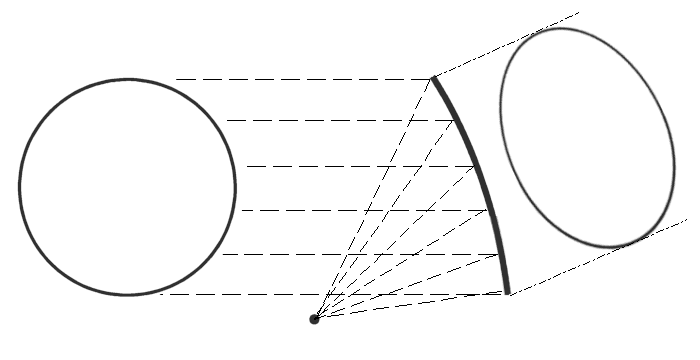
Figure 2: Geometry of offset parabolic dish antenna
In commercial offset antennas, such as satellite dishes, the section from the rotation-paraboloidal reflector body is not round but oval. The reflector of an effective offset antenna should have each of its borders at points of equal power density – with an eccentricity of the feeding horn this is oval or even egg-shaped. You can use the trace with a flashlight experiment: when the flashlight shines perpendicularly on a surface, the illuminated surface is round. If the flashlight shines obliquely on a surface, the illuminated surface is ovoid. Therefore, for example, a given commercial offset antenna for the reception of satellite TV has a width of 1.25 m and a height of 1.35 m. Due to the projection of this real area then a round effective antenna aperture appears (see Figure 2).

Figure 3: Offset antenna with antenna reflector as so-called “Orange-Peel Paraboloid”
Especially with 2D radar this round aperture is usually not desirable. The azimuth angle is required a small opening angle as possible but in the elevation angle is desired a given value in the range of 15 to 30 degrees. Therefore, a parabolic antenna for radar equipment is not just a simple squared section from a paraboloid (as shown in the fan beam antenna), but has a more rounded shape. The aim of this design is the most effective utilization of the reflector surface with the smallest possible area. Because the distances between the feeding horn and the different subareas of the reflector are different for an offset antenna, the radiation density at the outline borders caused by a primary radiator with mostly symmetric diagram is different. The further the reflectors subareas are away from the radiators, the lower the radiation density on the reflector surface. Some subareas, which are located at the outer edge are so involved less effective in forming of the antenna pattern. From a certain required minimum effectiveness, these ineffective subareas may be omitted. This creates a reflector shape that is reminiscent of a segment of an orange peel. Therefore, these shapes of the reflector are often referred to as a Orange-Peel Paraboloid or Orange-Peel Antenna.
Most radars with a parabolic antenna are using the principle of offset antenna. This structure also has the advantage in radar devices that the high transmit power is not reflected directly back to the radiator. The radiator would receive back this power: thus, the standing wave ratio would deteriorate on the line to the antenna. Therefore, the load of the transmitter's end stage is lower using an offset antenna.

