Slant Range
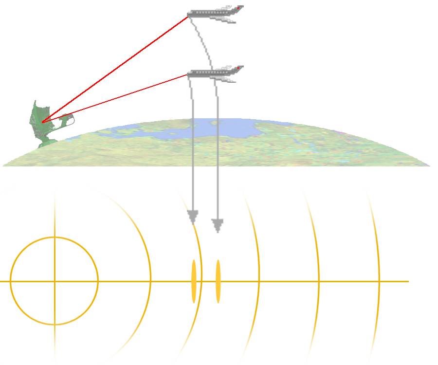
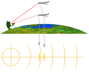
Figure 1: A different height causes a different range
Slant Range
The slant range is the length of the skywave path between target and radar, not the distance as measured along the Earth's surface (the so-called Down Range). As shown in Figure 1, the radar measures different ranges of two airplanes, which exactly one above the other flies (therefore having the same topographical distance to the radar set exactly).
This false measurement is corrected by a software module in modern radar units such as the RRP-117. These software modules then must also especially be adapted on the geographical coordinates of the radar units site, however. The calculation is very complicated and also requires some weather data to the correction.
Older 2D radar sets, like the ASR-910 still used in the air traffic management, cannot make this, unfortunately.
The operator must know and take into account automatically in his work here that the target of an airplane flying in a larger range is indicated on the scope in an even larger range as really!
Nevertheless, the measurement error is relatively small. The slant range to ground range distortion is much more pronounced in airborne SAR systems.
Calculation of the Down Range
Figure 2: trigonometrical connections without consideration of the earth's bend
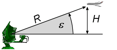
Figure 2: trigonometrical connections without consideration of the earth's bend
Figure 2: trigonometrical connections without consideration of the earth's bend
The range between a ground radar and the ground projection of the target is called the Down Range. It is very important to know over which one topographical point on the earth's surface the detected airplane is located exactly. For this reason, an electronic map always is projected onto the radar screen. It is expected by this map that it is as exact as possible. The calculation of the actual topographical range of a located aim, however, is very complicated in radar unit.
The calculated topographical range is under application of the trigonometrical connections
(shown in Figure 2):
Rtopogr. = R · cos ε
However, this would be valid only then, if the earth was a flat plate. The earth radius in addition also affects, however, as shown in Figure 3. Well, the actual topographical distance in proportion to the slant range measured by the radar unit depends on:
- the measured slant range,
- the actual height of the aim, and
- the actual earth radius valid for the radar units site.
Figure 3: trigonometrical connections including the consideration of the earth's bend
Figure 3: trigonometrical connections including the consideration of the earth's bend
Figure 3: trigonometrical connections including the consideration of the earth's bend
One can take the mathematical rule for the calculation from Figure 3. A triangle arises between
the points: center of the earth, the radar units site and the position of the aircraft.
The sides of this triangle are described by the cosine theorem and therefore by the equation:
R2 = re2 + (re + H)2 - 2re(re + H) · cos α
(re is the equivalent earth radius here).
Under the assumption that the earth is a sphere the section of the circumference of the earth
can be calculated with the help of a simple ratio from the complete circumference of the earth from
the angle α:
360° · Rtopogr. = α · 2π re
This section of the circumference of the earth can be considered an approximation for the actual
topographical range (here though still without consideration of the refraction).
In the practice, however, the propagation of the electromagnetic waves is also subject to refraction, this means, the transmitted beam of the radar unit isn't a straight side of this triangle but this side also is bent in addition into the dependence of
- the transmitted wavelength,
- the barometric pressure,
- the air temperature and
- the atmospheric humidity.
Well, the radar video map is inaccurate, if the software of the radar unit doesn't take this connection between slant range and topographical distance into account. And this is unfortunately always the case at 2D- radar units since these are missing the height information mandatory required for these calculations!