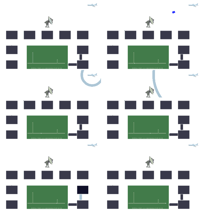
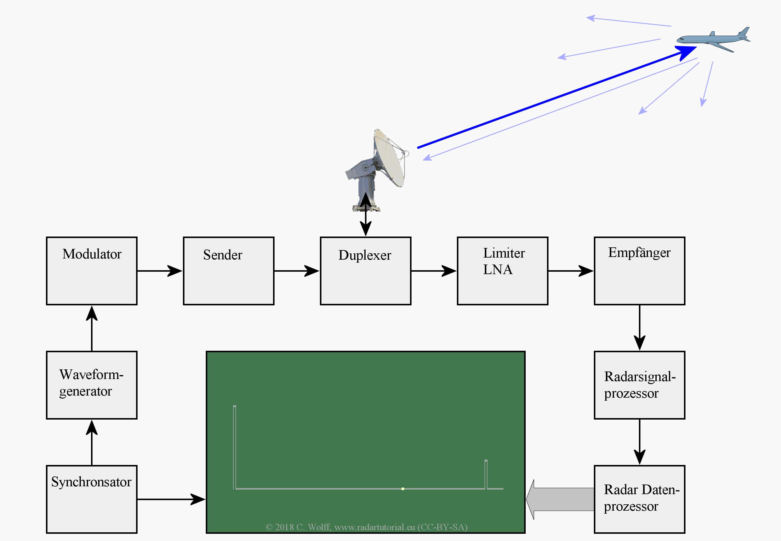
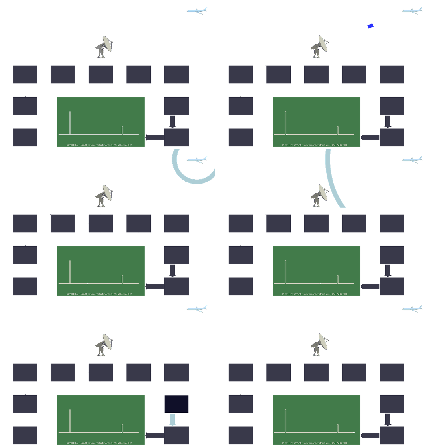
Universal Block Diagram of Pulse Radar

Figure 1: Universal Block Diagram of Pulse Radar

Figure 1: Universal Block Diagram of Pulse Radar

Figure 1: Universal Block Diagram of Pulse Radar
This block diagram may be used for your own lessons but there are no block labels in the animation and there is no background image (landscape).
These block labels can be placed in an own layer over the animation in e.g. MS-PowerPoint with text boxes in your own language version.
For a presentation with a light background color, you can use the following animation:
pulseradar-bright.gif (940×650px, 683 kByte).
Description of the modules of the block diagram
Synchronizer
The radar synchronizer provides all timestamps, trigger pulses, and switching gates. With the transmitter trigger pulse, it determines the starting point of the emission of the energy.
Waveform Generator
In modern radars, the waveform generator generates the complex transmission signal on the intermediate frequency. This also includes the duration of the transmitter's pulse. In earlier, simple pulse radars, it was integrated into the modulator as a pulse forming network.
Modulator
In more modern radars the modulator up-converts the transmitters waveform into the carrier frequency of the transmitter. In older radars, it produced only a high voltage pulse of defined length as an anode voltage for the self-oscillating transmitter tube.
Transmitter
The transmitter generates the energy of the radar pulse. More complex waveforms are boosted to the necessary power in a high power amplifier. Simple, internally unmodulated (keyed ON/OFF) pulses were generated in a self-oscillating high-power tube (for example, in a magnetron).
Duplexer
The duplexer is a transmit-receive switch. It switches the antenna to the transmitter during the transmit pulse and protects the receiver from being overloaded by the high transmit power. In the receiving time, it transmits the echo signals to the receiver with the least possible loss.
Sensitivity Time Control
Sensitivity Time Control is time-dependent gain control. In the near range, the echo signals are very strong, so they need only a small gain. At large distances, the echo signals are extremely weak, the gain must be regulated to a maximum. In order not to saturate the receiver, this regulation must be made as early as possible in the high-frequency range. In most cases, an additional limiter is integrated to protect the sensitive low-noise preamplifier stages in the receiver.
Receiver
The receiver converts the high-frequency signals into a lower intermediate frequency, which is easier to process.
At this intermediate frequency, the essential part of the amplification of the echo signals is provided.
In order to obtain the best possible dynamics, mostly logarithmic amplifiers are used.
Radar Signal Prozessor
The radar signal processor still processes the echo signals in real time. They can already be digitized here but are still in a fixed temporal context to the transmitted pulse. Here, many filters can be used in parallel, from which only this one output signal is used, which has the largest signal-to-noise ratio. For further processing, however, the name of the filter used must be forwarded with, as this is an important indicator in the target identification.
Radar Daten Prozessor
The radar data processor only processes the digital description of the echo signal. Since processing operations of different lengths have no fixed relation to the start impulse of the transmitter, these data are no longer in real time. For this purpose, the dataset got a timestamp at the begin of the processing, so that the data can be displayed in the correct time reference.
Radar Indicator
Representing a variety of radar vision devices, a simple oscilloscope is shown here as an analog A-scope. The linear X-deflection is scaled to the propagation velocity of the electromagnetic waves in space. The transmission pulse also passes the reception path. This compensates for time delays in the internal circuits on the oscilloscope: The runtime (and thus the distance of the target) is measured from the leading edge of the transmitted pulse to the leading edge of the echo signal shown.
